Medical physics and biotechnology: highlights of 2025
This year saw Physics World report on a raft of innovative and exciting developments in the worlds of medical physics and biotech. These included novel cancer therapies using low-temperature plasma or laser ablation, intriguing new devices such as biodegradable bone screws and a pacemaker smaller than a grain of rice, and neural engineering breakthroughs including an ultrathin bioelectric implant that improves movement in rats with spinal cord injuries and a tiny brain sensor that enables thought control of external devices. Here are a few more research highlights that caught my eye.
Vision transformed
One remarkable device introduced in 2025 was an eye implant that restored vision to patients with incurable sight loss. In a clinical study headed up at the University of Bonn, participants with sight loss due to age-related macular degeneration had a tiny wireless implant inserted under their retina. Used in combination with specialized glasses, the system restored the ability to read in 27 of 32 participants followed up a year later.
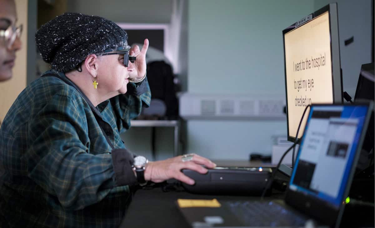
We also described a contact lens that enables wearers to see near-infrared light without night vision goggles, reported on an fascinating retinal stimulation technique that enabled volunteers to see colours never before seen by the human eye, and chatted with researchers in Hungary about how a tiny dissolvable eye insert they are developing could help astronauts suffering from eye conditions.
Radiation therapy advances
2025 saw several firsts in the field of radiation therapy. Researchers in Germany performed the first cancer treatment using a radioactive carbon ion beam, on a mouse with a bone tumour close to the spine. And a team at the Trento Proton Therapy Centre in Italy delivered the first clinical treatments using proton arc therapy – a development that made it onto our top 10 Breakthroughs of the Year.
Meanwhile, the ASTRO meeting saw Leo Cancer Care introduce its first upright photon therapy system, called Grace, which will deliver X-ray radiation to patients in an upright position. This new take on radiation delivery is also under investigation by a team at RaySearch Laboratories, who showed that combining static arcs and shoot-through beams could increase plan quality and reduce delivery times in upright proton therapy.
Among other new developments, there’s a low-cost, dual-robot radiotherapy system built by a team in Canada and targeted for use in low-resource settings, a study from Australia showing that combining microbeam radiation therapy with targeted radiosensitizers can optimize brain cancer treatment, and an investigation at Moffitt Cancer Center examining how skin luminance imaging improves Cherenkov-based radiotherapy dosimetry.
The impact of AI
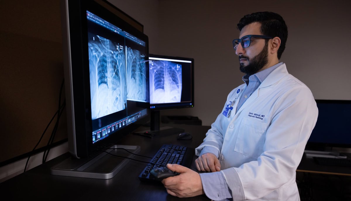
It’s particularly interesting to examine how the rapid evolution of artificial intelligence (AI) is impacting healthcare, especially considering its potential for use in data-intensive tasks. Earlier this year, a team at Northwestern Medicine integrated a generative AI tool into a live clinical workflow for the first time, using it to draft radiology reports on X-ray images. In routine use, the AI model increased documentation efficiency by an average of 15.5%, while maintaining diagnostic accuracy.
Other promising applications include identifying hidden heart disease from electrocardiogram traces, contouring targets for brachytherapy treatment planning and detecting abnormalities in blood smear samples.
When introducing AI into the clinic, however, it’s essential that any AI-driven software is accurate, safe and trustworthy. To help assess these factors, a multinational research team identified potential pitfalls in the evaluation of algorithmic bias in AI radiology models, suggesting best practices to mitigate such bias.
A quantum focus
Finally, with 2025 being the International Year of Quantum Science and Technology, Physics World examined how quantum physics looks set to play a key role in medicine and healthcare. Many quantum-based companies and institutions are already working in the healthcare sector, with quantum sensors, in particular, close to being commercialized. As detailed in this feature on quantum sensing, such technologies are being applied for applications ranging from lab and point-of-care diagnostics to consumer wearables for medical monitoring, body scanning and microscopy.
Alongside, scientists at Jagiellonian University are applying quantum entanglement to cancer diagnostics and developing the world’s first whole-body quantum PET scanner, while researchers at the University of Warwick have created an ultrasensitive magnetometer based on nitrogen-vacancy centres in diamond that could detect small cancer metastases via keyhole surgery. There’s even a team designing a protein qubit that can be produced directly inside living cells and used as a magnetic field sensor (which also featured in this year’s top 10 breakthroughs).
And in September, we ran a Physics World Live event examining how quantum optics, quantum sensors and quantum entanglement can enable advanced disease diagnostics and transform medical imaging. The recording is available to watch here.
The post Medical physics and biotechnology: highlights of 2025 appeared first on Physics World.